
Related News
- 00
0000-00
How to size heavy-duty loaders for North American mining operations - 00
0000-00
How altitude affects mining excavator performance in Latin America - 00
0000-00
Caterpillar Launches New Cat 6060 and Upgraded Autonomous Mining System - 00
0000-00
When does eco-friendly construction equipment pay for itself? - 00
0000-00
Will a wheel loader quick coupler fit your existing attachments?
Why do hydraulic attachments standards matter so much in real equipment matching?
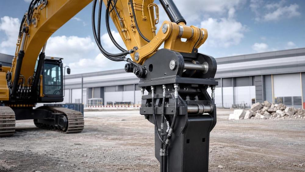
Hydraulic attachments standards sit at the center of machine compatibility. They are not just catalog details or workshop references.
In earthmoving, grading, demolition, and compact construction, one wrong specification can create leakage, unstable tool behavior, or repeated downtime.
That is why hydraulic attachments standards are watched closely across crawler excavators, skid steer loaders, wheel loaders, and specialized carrier platforms.
At EMD, compatibility is usually treated as a system question. Breakout force, attachment demand, control logic, and future fleet flexibility all interact.
In simple terms, standards help answer one practical question: will this attachment work safely, efficiently, and repeatedly on this machine?
The answer depends on several linked items, not one rating alone. Flow, pressure, mounting geometry, coupler interface, drain requirements, and controls all matter.
In demanding applications, hydraulic mismatch does more than reduce output. It can accelerate heat buildup, damage seals, stress auxiliary lines, and shorten component life.
That is why hydraulic attachments standards remain essential in fleets moving toward electrification, automation, and remote operation, where predictable interface behavior matters even more.
Which key specs usually decide whether an attachment is truly compatible?
Most compatibility problems come from a small set of specifications. The mistake is assuming one matched number means the whole package is correct.
A better reading of hydraulic attachments standards starts with these core checks:
- Auxiliary flow rate: measured in L/min or gpm, this controls tool speed and response.
- Operating pressure: this determines whether the attachment can reach its designed force output.
- Peak or relief pressure: this protects the circuit when shock loads or overload conditions appear.
- Mounting dimensions: pin diameter, pin centers, ear width, and bracket geometry must physically match.
- Coupler type: manual, hydraulic, OEM-specific, or common quick-coupler systems can change fitment completely.
- Return line and case drain requirements: some high-performance tools need dedicated low-backpressure return paths.
- Control interface: on-off, proportional, pedal, joystick, software mapping, or CAN-based integration may be required.
For example, a hydraulic breaker may fit the coupler and still fail in practice because the carrier cannot supply the required return flow conditions.
A tiltrotator or smart grading attachment raises the bar further. Beyond oil supply, it may require electronic communication and calibration support.
This is where hydraulic attachments standards become more than dimensional references. They shape the full machine-to-tool operating relationship.
A quick judging table helps separate workable matches from risky ones
In actual screening, a compact decision table often reveals issues faster than reading several spec sheets line by line.
This kind of checklist is especially useful when reviewing mixed fleets or comparing standard and high-flow machines.
Is a matching coupler enough, or is that where many evaluations go wrong?
A matching coupler is necessary, but it is rarely enough. This is one of the most common misunderstandings around hydraulic attachments standards.
Physical fit only confirms that the attachment can connect. It does not confirm hydraulic performance, safe pressure behavior, or control-system readiness.
In skid steer applications, this is often visible with trenchers, planers, and brush cutters. The plate fits, but the hydraulic demand exceeds the carrier.
On excavators, the same issue appears with breakers, compactors, grapples, and rotating demolition tools. Bracket compatibility can hide deeper circuit conflicts.
Another complication is coupler variation itself. OEM couplers, regional quick-coupler patterns, and aftermarket adapter brackets do not always behave the same under load.
Even when pin dimensions line up, breakout geometry, weight distribution, and attachment center of gravity may shift machine stability or usable force.
That matters on compact carriers, but also on larger crawler excavators working in quarry, pipeline, or demolition conditions where hydraulic tools face repeated shock loads.
A more reliable approach is to treat coupler fit as the first gate, not the final approval.
How should flow, pressure, and control logic be judged for different attachment types?
Not all hydraulic tools consume oil in the same way. That is why hydraulic attachments standards must be read in the context of attachment behavior.
A breaker often needs a narrow flow and pressure window. Too little flow reduces impact frequency. Too much can create harmful heat and erratic operation.
A hydraulic auger or cold planer usually responds more to continuous flow stability. Pressure still matters, but speed consistency may be the bigger issue.
Rotating grapples, tilt buckets, and compactors can be more forgiving mechanically, yet they still depend on valve response and proper hose sizing.
Smart attachments introduce another layer. Precision grading tools, tiltrotators, and some autonomous-ready systems may require proportional circuits and software-defined control mapping.
In these cases, standard hydraulic numbers do not tell the whole story. Machine display integration, auxiliary presets, and sensor communication may affect usability.
This is increasingly relevant as fleets move toward low-emission machines, electro-hydraulic control, and remote operation in hazardous or tightly managed job sites.
A practical evaluation usually asks three linked questions:
- Can the carrier sustain the required flow without excessive heat?
- Does the pressure setting match the tool’s operating and protection limits?
- Will the control interface deliver the precision or cycling behavior the task requires?
When all three align, hydraulic attachments standards become actionable selection tools rather than static reference tables.
What are the most expensive mistakes when reading hydraulic attachments standards?
The costliest mistakes usually come from partial reading. One number is checked, four others are assumed, and the mismatch appears only after delivery.
Several errors show up repeatedly across construction and earthmoving fleets:
- Using maximum pressure instead of continuous operating pressure when comparing machine and attachment data.
- Ignoring return-line backpressure requirements on high-performance motors and rotating tools.
- Assuming all quick couplers within one size class share the same geometry.
- Forgetting attachment weight and its effect on reach, lift chart limits, and machine stability.
- Overlooking electronic presets, software locks, or valve calibration needed for modern attachment control.
- Treating aftermarket adapters as neutral, even when they alter geometry, stress paths, or maintenance access.
In practice, these mistakes affect cost in several ways. There may be rework, hose replacement, lost operating hours, or warranty disputes.
The hidden cost is often lower asset utilization. A machine that should move between attachments quickly becomes tied to a narrow task window.
For fleets pursuing higher uptime and lower emissions intensity, that kind of underuse becomes a strategic problem, not just a workshop issue.
What is the smartest next step before approving an attachment specification?
The most effective next step is to build a short validation sequence before any final approval or field deployment.
Start with the machine’s verified auxiliary hydraulic data, not a sales summary. Then compare it against the attachment’s full operating envelope.
After that, confirm physical mounting, coupler pattern, hose routing, return requirements, and control compatibility in one document.
Where the application is sensitive, include operating context. Quarry breaking, urban utility work, road grading, demolition, and mine support all stress systems differently.
It also helps to separate must-match items from adjustable items. Some settings can be tuned. Others, such as backpressure limits or bracket geometry, cannot be negotiated safely.
A concise review workflow may include:
- Confirm rated flow, continuous pressure, and relief settings.
- Verify coupler pattern, mounting dimensions, and attachment weight.
- Check return, drain, and hose sizing requirements.
- Review controls, presets, and software integration needs.
- Assess duty cycle, ambient temperature, and task-specific load profile.
That process keeps hydraulic attachments standards tied to real machine behavior. It also supports the broader industry shift toward reliable, data-backed equipment decisions.
The main point is straightforward. Compatibility is earned through complete verification, not assumed from one matched interface.
When reviewing the next attachment, compare the full hydraulic path, the mounting system, and the control layer together. That is where the most dependable decisions are made.